Technical Data Sheet
Columns
SSOUNDS
SS-LC83
SSOUNDS LC8.3
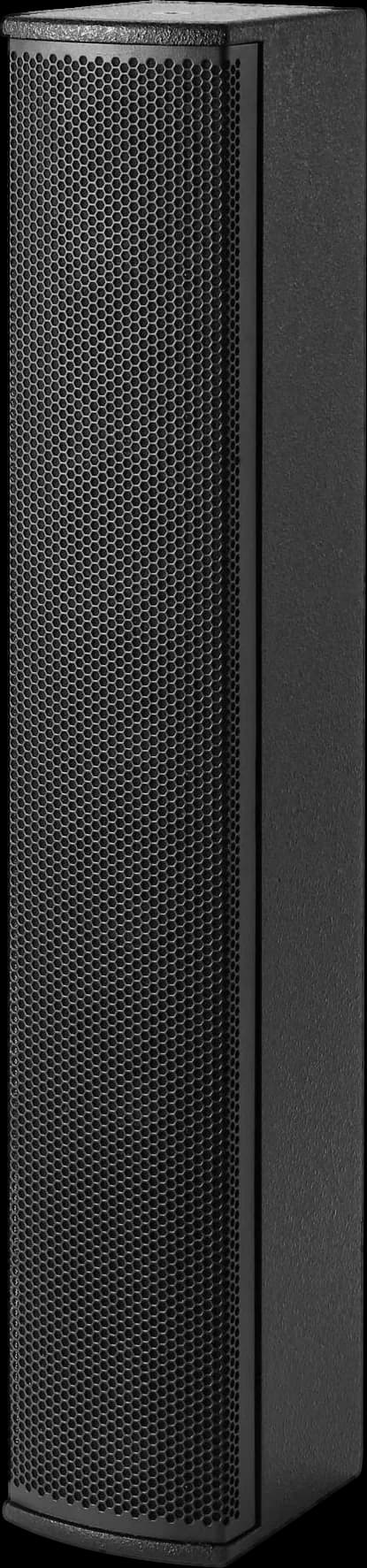
8 × 3″ full-range column for speech in halls, offices and long atria, 100° × 18°.
Part of the LC System. Eight 3″ drivers, 100° × 18°: speech in halls, offices and long atria. LC stands for Line Column. Full system documentation at s-soundspro.com/systems/lc.
At a glance
- Model / SKU
- SS-LC83
- Category
- Columns
- Brand
- SSOUNDS
- Drive
- Passive
- Power
- 200 W
- Condition
- New
Applications
Overview
In a reverberant room the energy that misses the audience comes back late and buries the next syllable. The LC8.3 stacks eight 3″ full-range drivers into a 720 mm line, which holds the vertical pattern to 18° so the sound lands on the listening plane and less of it reaches the ceiling. The horizontal stays 100° wide. It suits lecture rooms, shop floors, long atria and the side walls of a house of worship, and it is the column we specify where a speech-first position has to cover a commercial space without a ceiling grid.
- 8 × 3″ full-range drivers in one vertical line
- 100° (H) × 18° (V) coverage
- 110 Hz to 18 kHz (−10 dB)
- 118 dB continuous, 124 dB peak at 1 m
- 200 W AES power handling, 4 Ω
- 4 × NL4 speakON, wall bracket, 8.6 kg
Specifications
General
| Type | Passive column array, full-range |
Acoustic performance
| Frequency response2 | 110 Hz – 18 kHz (−10 dB) |
| Coverage4 | 100° (H) × 18° (V) |
| Maximum SPL1 | 118 dB continuous · 124 dB peak @ 1 m |
| Sensitivity3 | 95 dB (1 W @ 1 m) |
Transducers & components
| Drivers | 8 × 3″ full-range, 0.75″ voice coil |
Electrical
| Power handling (AES / peak)5 | 200 W / 800 W |
| Nominal impedance6 | 4 Ω |
Connectors & I/O
| Connectors | 4 × NL4 speakON |
Rigging & mounting
| Mounting | Wall bracket |
Physical & construction
| Dimensions (H × W × D)8 | 720 × 124 × 155 mm |
| Net weight7 | 8.6 kg / 19 lb |
| Enclosure | Wood |
Notes
- 1.Maximum SPL is the peak level at 1 m, driven with pink noise at crest factor 4 to the clipping point of the recommended amplifier, with the SSOUNDS system preset applied. Full-range enclosures are specified under free-field conditions; figures marked half-space are specified over a reflecting plane, the condition subwoofers are deployed in, which adds approximately 6 dB.
- 2.Frequency response is specified on axis at 1 m in a free field. The tolerance the figure is referenced to is stated alongside it; where no tolerance is given, the figure is the −6 dB bandwidth.
- 3.Sensitivity is specified at 1 W into the nominal impedance at 1 m on axis, averaged across the pass band of the enclosure.
- 4.Coverage angles are nominal −6 dB values averaged across the pass band. Per-octave directivity data is available from SSOUNDS system design support for prediction and modelling.
- 5.Power handling is rated to AES2 using pink noise with a 6 dB crest factor over a two-hour period. Programme power is twice the AES rating; peak power is four times.
- 6.Nominal impedance is the manufacturer's rating for amplifier load calculation; minimum impedance across the operating band may be lower.
- 7.Net weight excludes packaging, flight case, accessories and optional rigging hardware.
- 8.Dimensions are stated in millimetres and exclude protruding rigging hardware, handles and connector panels unless noted.
- 9.All figures are typical values for production units specified under the conditions above. Individual units may vary within published tolerances.
Response
Frequency response: 110 Hz to 18 kHz (−10 dB) · 1/24-octave smoothed
−6 dB horizontal beamwidth: 100° nominal
Plot conditions. Curves are generated by the SSOUNDS engineering toolchain from this product's specification. Frequency response is shown 1/24-octave smoothed, normalised to the midband reference, with the passband corners at the stated tolerance; response varies within ±1 dB across the passband with a subtle shelf in the top octave. Magnitude slopes are 24 dB/octave beyond the passband corners. The beamwidth curve shows the −6 dB included angle: nominal coverage holds down to the pattern-control limit set by the cabinet width (f ≈ c/w) and widens below it.
Directivity
Lines of equal sound pressure. Blue: -6 dB. Dashed: -12 dB. White region holds within 6 dB of on-axis.
Lines of equal sound pressure. Blue: -6 dB. Dashed: -12 dB. White region holds within 6 dB of on-axis.
Normalised to on-axis. Rings at 6 dB intervals to a -30 dB centre. 1/3-octave band power.
Normalised to on-axis. Rings at 6 dB intervals to a -30 dB centre. 1/3-octave band power.
Charts span 110 Hz to 16 kHz, this cabinet's own operating band.
Chart conditions. Directivity charts are computed by the SSOUNDS system prediction engine as a phase-coherent wave solution of this product's driver complement: each way represented by its physical radiator (rigid-piston cones with real diameters and spacings; waveguides as continuous mouth apertures, holding the rated coverage on a flare-controlled axis above the mouth's pattern-control limit and radiating the mouth's own diffraction limit on a wavefront-shaped axis; a horn-loaded mid shares the high-frequency mouth), summed as complex pressure through crossovers at the published points in the topology the cabinet is driven with (linear-phase FIR where the ways run on separate channels of a system DSP amplifier, Linkwitz-Riley where a passive network splits them), with way alignment referenced on axis and 1/24-octave band-power resolution. Single-cabinet vertical figures are free-field beamwidths of one element; the published per-element vertical coverage of a line array is its rigging splay, the sector one element covers in a curved hang. Cabinet edge diffraction, horn loading detail, driver breakup and production tolerances are outside the computation. Directivity files for prediction software (GLL/CLF) are issued from measured data only.
Downloads & data files
- SSOUNDS LC8.3: User Manualmanual
- Directivity table, horizontal (CSV) / verticalcsv
- SSOUNDS LC8.3: Technical Data Sheetdatasheet
Loudspeaker data files for prediction software (GLL / CLF for EASE), 2D and 3D drawings and certification documents are issued on request. Contact support@s-soundspro.com and we will send the current release for this model.
Architectural & engineering specification
The unit shall be of the SSOUNDS LC8.3 type, configured as a passive column array, full-range. The unit shall be capable of meeting the following performance criteria: a frequency response of 110 Hz – 18 kHz (−10 dB); a maximum sound pressure level of 118 dB continuous, 124 dB peak @ 1 m; a sensitivity of 95 dB (1 W @ 1 m); nominal coverage of 100° (H) × 18° (V). Electrically the unit shall provide a power handling of 200 W / 800 W, a nominal impedance of 4 Ω. Connection shall be by 4 × NL4 speakON. The unit shall be constructed of Wood, measuring 720 × 124 × 155 mm, and shall weigh 8.6 kg / 19 lb. Rigging provision shall be Wall bracket. The unit shall be covered by the manufacturer's two (2) year limited warranty and shall be supplied by SSOUNDS or an SSOUNDS-authorised distributor. No alternate shall be accepted without prior written approval of the consultant or specifying engineer.
Safety & compliance
Read this section before specifying, installing or operating this product. It summarises the safety requirements set out in full in the product documentation supplied with the unit; where the two differ, the product documentation takes precedence.
- Suspension & rigging
- Overhead suspension is potentially hazardous and must be carried out only by trained and competent personnel using SSOUNDS-approved hardware, within the working load limits and array configurations published in the relevant SSOUNDS rigging documentation. Never exceed the stated number of enclosures per array or the stated splay limits. Inspect all rigging components, pins and retaining clips before every deployment and withdraw from service any component that is deformed, corroded or of unknown history. Secondary safety attachment is required where local regulation calls for it. SSOUNDS accepts no liability for systems suspended using non-approved hardware or outside published limits.
- Sound pressure level & hearing
- This equipment is capable of producing sound pressure levels that cause permanent hearing damage. Do not operate at high level in close proximity, and ensure that operators, performers and audience exposure complies with applicable occupational noise-exposure regulation. Provide hearing protection where exposure limits may be exceeded.
- Environment & mechanical
- Unless a published IP rating states otherwise, this product is intended for indoor use or for outdoor use under cover, and must be protected from rain, standing water and prolonged direct sun. Ensure ventilation openings are unobstructed. Stack, pole-mount and transport only as described in the product documentation, and secure the product against toppling wherever the public has access.
- Disposal
- At end of life, dispose of the product and any packaging in accordance with local regulation for electrical and electronic equipment. Do not dispose of electronic components in general waste.
Limited warranty: two (2) years
SSOUNDS products are warranted against defects in materials and workmanship for a period of two (2) years from the original date of purchase by the end user. Within that period SSOUNDS will, at its option, repair or replace the defective item with no charge for parts or labour. The item must be adequately packaged and dispatched, carriage pre-paid, to SSOUNDS or an SSOUNDS-authorised service centre, accompanied by proof of purchase and a returns reference issued in advance by SSOUNDS. Unauthorised repair, modification or removal of serial-number labelling voids this warranty.
This warranty does not cover
- Cosmetic wear, finish, grille cloth, paintwork and consumable parts.
- Damage caused by misuse, abuse, accident, neglect, or operation outside the published ratings on this sheet.
- Damage caused by transport or handling after delivery, or by inadequate packaging on return.
- Damage caused by mains or generator supply faults (over-voltage, under-voltage, phase imbalance, surge or incorrect earthing) or by lightning.
- Water, dust or corrosion ingress on products not carrying a published IP rating for the conditions of use.
- Damage resulting from amplification or processing outside the recommended configuration on this sheet, or from third-party presets.
- Products not purchased from SSOUNDS or an SSOUNDS-authorised distributor.
This warranty is in addition to, and does not affect, any statutory rights the purchaser may have under applicable consumer law. It is the sole warranty offered; no other warranty, express or implied, is given.
Warranty claims and returns references: support@s-soundspro.com · +44 20 3769 6537
Legal notice
All information on this data sheet is subject to change without notice. SSOUNDS reserves the right to alter specification, design and construction in the course of continuous product development.
Specifications, drawings and images are provided for guidance in system design and tender documentation. Where a figure is critical to a design, confirm it in writing with SSOUNDS before committing to a specification.
All text, images and drawings herein are the property of SSOUNDS. All trademarks and registered trademarks are the property of their respective owners.