Ceiling Speaker Placement: The Complete Guide
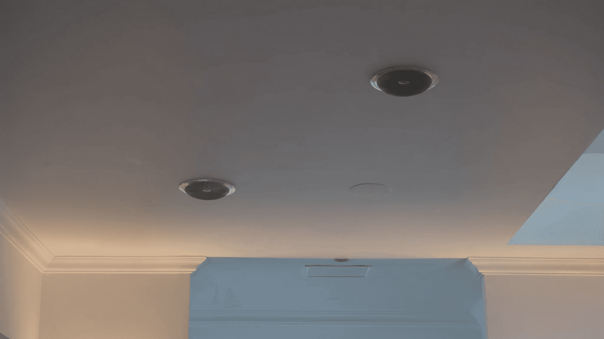
Proper ceiling speaker placement is critical for achieving uniform coverage, speech intelligibility, and avoiding dead zones or hot spots in distributed sound systems. This guide covers spacing rules, listening height considerations, 70/100V line coverage calculations, overlap requirements, edge distances, and practical installation tips to help you design a professional-grade system.
Key takeaways
- Calculate coverage diameter using mounting height, ear height, and speaker coverage angle.
- Space speakers 1.5–2× the coverage diameter apart for even SPL (±3 dB).
- In 70/100V systems, sum of tap settings should not exceed 80% of amplifier power.
- Ensure -6 dB coverage circles overlap by at least 50% to avoid dead zones.
- Keep speakers at least half a coverage diameter away from walls to prevent hotspots.
- Use simulation software and on-site measurements to verify placement.
Understanding Coverage Angle and Listening Height
The coverage angle of a ceiling speaker (typically 90°–120° for common models) determines the area it can cover at a given listening height. The listening height is the distance from the speaker to the ears of the audience, usually around 1.2–1.5 m above the floor for seated listeners or 1.6–1.8 m for standing. To calculate the coverage diameter at ear level, use: Diameter = 2 × (mounting height – ear height) × tan(coverage angle/2). For example, a speaker with a 100° coverage angle mounted at 3 m with a 1.2 m ear height covers a diameter of about 4.3 m.
Lower mounting heights reduce coverage diameter but increase SPL at ear level, while higher ceilings require more speakers or wider coverage angles. Always measure from the speaker's baffle to the listener's ear, not to the floor. SSOUNDS ceiling speakers are designed with optimized coverage patterns to simplify these calculations.
Spacing Rules for Even Coverage
The golden rule for ceiling speaker spacing is to maintain a center-to-center distance equal to 1.5 to 2 times the coverage diameter at ear level. For overlapping coverage, the typical target is 100% overlap at the edge of coverage (i.e., the -6 dB point of one speaker aligns with the -6 dB point of the adjacent speaker). This ensures that the combined SPL variation across the listening plane stays within ±3 dB.
For example, if each speaker covers a 4 m diameter at ear level, spacing should be 2–2.7 m. Tighter spacing reduces SPL variation but increases cost; wider spacing creates dead zones. In critical applications like conference rooms or houses of worship, aim for 1.5× diameter spacing. For background music in retail, 2× may suffice. SSOUNDS recommends using acoustic simulation software to verify coverage before installation.
70V/100V Line Coverage Maths
In distributed 70V/100V systems, the number of speakers per amplifier channel is limited by total power tap settings. Each speaker has a tap (e.g., 1.5W, 3W, 6W, 12W) that determines its output SPL. To calculate coverage, first determine the required SPL at ear level. Then, using the speaker's sensitivity (dB SPL at 1W/1m), compute the SPL at listening distance: SPL = sensitivity + 10 × log(power tap) – 20 × log(distance in m).
Ensure that the sum of all tap settings does not exceed 80% of the amplifier's rated power (for headroom). For example, a 120W amplifier can drive up to 16 speakers tapped at 6W each (96W total). Coverage area per speaker is independent of tap setting, but higher taps increase SPL and can reduce the number of speakers needed. SSOUNDS 70V/100V ceiling speakers provide multiple taps for flexibility.
Overlap and Edge Distance Requirements
Overlap between adjacent speaker coverage areas is essential to avoid dead zones. The industry standard is to ensure that the -6 dB coverage circles overlap by at least 50% of their diameter. This means the distance between speaker centers should be no more than 1.5 times the coverage diameter. For edge distance, speakers should be placed no closer than half the coverage diameter from walls to prevent excessive reflections and uneven coverage near boundaries.
In rectangular rooms, use a grid pattern: start by placing speakers in a square or staggered grid. Staggered (offset) grids often provide smoother coverage in larger spaces. For irregular rooms, prioritize covering seating areas first, then fill in. Always check for obstructions like beams, HVAC vents, or lighting that can block sound. SSOUNDS engineers recommend on-site measurement with a sound level meter to fine-tune placement.
Avoiding Hotspots and Dead Zones
Hotspots occur when speakers are too close to each other or to walls, causing constructive interference and excessive SPL in certain areas. Dead zones happen when spacing is too wide or coverage angles are too narrow. To avoid hotspots, maintain consistent spacing and avoid placing speakers directly above listeners' heads unless the coverage angle is very wide. Use baffle-mounted speakers with aimable tweeters to direct sound away from walls.
For dead zones, ensure that the -6 dB coverage circles overlap as described. In multi-zone systems, use separate amplifier channels for zones with different ceiling heights. SSOUNDS ceiling speakers feature wide-dispersion drivers and optional waveguide accessories to fine-tune coverage and minimize interference.
Practical Installation Tips
Always use a laser distance measurer or string lines to mark speaker positions on the ceiling before cutting holes. Verify that the ceiling structure (e.g., drop ceiling tiles, drywall) can support the speaker weight. For 70V/100V systems, use proper gauge wire (typically 18–14 AWG) to minimize line loss over long runs. Daisy-chain speakers in a loop or star configuration, but ensure total impedance is within amplifier limits.
After installation, test each speaker with a polarity checker and measure SPL at multiple listening positions. Adjust tap settings if some areas are too loud or too quiet. For critical applications, consider using DSP-based equalization to smooth frequency response. SSOUNDS provides detailed installation manuals and technical support for all ceiling speaker models.
Frequently asked
What is the ideal spacing for ceiling speakers in a conference room?
For a conference room with a 2.7 m ceiling and seated listeners (ear height 1.2 m), use speakers with a 100° coverage angle. Coverage diameter at ear level is about 3.6 m. Space them 1.5× that (5.4 m) for even coverage, but tighter spacing (e.g., 3 m) is better for speech intelligibility.
How do I calculate the number of ceiling speakers needed for a room?
Divide the room length and width by the recommended spacing (e.g., 1.5× coverage diameter). Round up to the nearest integer for each dimension. Multiply to get the total number. Then verify total power tap sum does not exceed amplifier capacity.
Can I mix different ceiling speaker models in the same zone?
It's not recommended because different models have different coverage angles, sensitivity, and frequency response, leading to uneven coverage. Use identical models within a zone for consistent performance.
What is the difference between 70V and 100V systems?
Both are constant-voltage systems. 100V is common in Europe and allows longer cable runs with less loss for the same power. 70V is typical in North America. The speakers are similar but must match the system voltage. SSOUNDS offers both versions.
How do I avoid feedback from ceiling speakers in a room with microphones?
Keep speakers at least 2 m away from microphones. Use narrow coverage speakers pointed away from mic positions. Apply equalization to reduce room modes. In 70V systems, lower tap settings reduce SPL and feedback risk.
Building or upgrading a system?
SSOUNDS engineers and manufactures professional PA worldwide — from a single room to stadium scale.